●Product Description
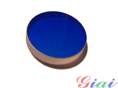
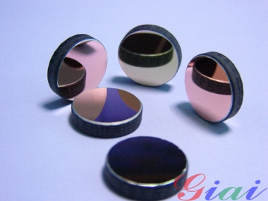
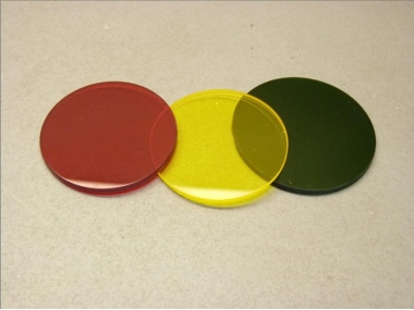
Our Bandpass Filters pass a narrow spectral band of UV, visible, or NIR radiation and reject out-of-band wavelengths from the X-ray to the far IR. Applications include spectral radiometry, medical diagnostics, chemical analysis, colorimetry, astronomy, and wherever spectral isolation is required.
●Product Detail
Giai Bandpass Filters are manufactured using methods and materials designed to deliver the highest spectral performance
Bandpass filters transmit light only within a defined spectral band ranging from less than one to many nanometers wide. They are used in a wide variety of applications where spectral isolation is required. Bandpass filters are preferable to monochromators because of their higher transmission and better signal-to-noise.
●Specifications
|
Minimum Active Area |
20.2 mm diameter for round filters;
45.5 mm sq for square filters |
|
Surface Quality |
80-50 scratch-dig; F/F per MIL-F-48616 |
|
Size Tolerance |
+0/-0.5 mm |
|
Thickness |
£7.6 mm |
|
Out-of-Band Blocking |
Xray–Far IR, T£0.01% or 10-4 (a crossover leak may be present on some models - see data curves) |
|
Wavelength Shift with Temperature |
0.01 to 0.02 nm/° C |
|
Specification Temperature |
23 °C |
|
Temperature Range |
-50°C to +100°C (70°C for Mercury Line Filters) |
|
Humidity Resistance |
Per MIL-STD-810E, method 507.3, procedure III, modified to 5 cycles |
|
Cleaning |
Non-abrasive method, acetone or isopropyl alcohol on lens tissue recommended |
|
Damage Threshold |
Not for high power lasers |
|
Data Curve Information |
Bandshape specifications and marker wavelengths are provided as approximate reference data only
|
|
Model
|
Center
Wavelength
(nm) |
FWHM
(nm) |
Minimum Peak
Transmission
(%) |
Effective Index
of Refraction ne |
|
80 mm square |
|
20BPF25-400 |
400±3.5 |
25±3.5 |
35 |
1.55 |
|
20BPF10-410 |
410±2 |
30±2 |
45 |
1.5 |
|
20BPF10-420 |
420±2 |
30±2 |
45 |
1.5 |
|
20BPF10-430 |
430±2 |
30±2 |
45 |
1.5 |
|
20BPF10-440 |
440±2 |
30±2 |
45 |
1.5 |
|
20BPF10-450 |
450±2 |
30±2 |
45 |
1.5 |
|
20BPF25-450 |
450±3.5 |
45±3.5 |
45 |
2.0 |
|
20BPF10-460 |
460±2 |
30±2 |
50 |
2.0 |
|
20BPF10-470 |
470±2 |
30±2 |
50 |
2.0 |
|
20BPF10-480 |
480±2 |
30±2 |
50 |
2.0 |
|
20BPF10-490 |
490±2 |
10±2 |
50 |
2.0 |
|
20BPF10-500 |
500±2 |
10±2 |
50 |
2.0 |
|
20BPF25-500 |
500±3.5 |
25±3.5 |
50 |
2.0 |
|
20BPF10-510 |
510±2 |
30±2 |
50 |
2.0 |
|
20BPF10-520 |
520±2 |
30±2 |
50 |
2.0 |
|
20BPF10-530 |
530±2 |
30±2 |
50 |
2.0 |
|
20BPF10-540 |
540±2 |
10±2 |
50 |
2.0 |
|
20BPF10-550 |
550±2 |
10±2 |
50 |
2.0 |
|
20BPF25-550 |
550±3.5 |
25±3.5 |
50 |
1.5 |
|
20BPF10-560 |
560±2 |
30±2 |
50 |
2.0 |
|
20BPF10-570 |
570±2 |
30±2 |
50 |
2.0 |
|
20BPF10-580 |
580±2 |
30±2 |
50 |
2.0 |
|
20BPF10-590 |
590±2 |
30±2 |
50 |
2.0 |
|
20BPF10-600 |
600±2 |
30±2 |
50 |
2.0 |
|
20BPF25-600 |
600±3.5 |
45±3.5 |
50 |
1.5 |
|
20BPF10-610 |
610±2 |
30±2 |
50 |
2.0 |
|
20BPF10-620 |
620±2 |
25±2 |
50 |
2.0 |
|
20BPF10-630 |
630±2 |
30±2 |
50 |
2.0 |
|
20BPF10-640 |
640±2 |
10±2 |
50 |
2.0 |
|
20BPF10-650 |
650±2 |
10±2 |
50 |
2.0 |
|
20BPF25-650 |
650±3.5 |
25±3.5 |
50 |
1.5 |
|
20BPF10-660 |
660±2 |
50±2 |
50 |
2.0 |
|
20BPF10-670 |
670±2 |
31±2 |
50 |
2.0 |
|
20BPF10-680 |
680±2 |
31±2 |
50 |
2.0 |
|
20BPF10-690 |
690±2 |
21±2 |
50 |
2.0 |
|
20BPF10-700 |
700±2 |
20±2 |
50 |
2.0 |
|
20BPF25-700 |
700±3.5 |
35±3.5 |
50 |
1.5 |
|
20BPF10-750 |
750±2 |
30±2 |
50 |
2.0 |
|
20BPF25-750 |
750±3.5 |
25±3.5 |
50 |
1.5 |
|
20BPF10-800 |
800±2 |
30±2 |
45 |
1.47 |
|
20BPF10-850 |
850±2 |
30±2 |
45 |
1.47 |
|
20BPF10-900 |
900±2 |
30±2 |
45 |
1.47 |
